
Every dimmable cob led strip is dimmable, in the sense that the strip itself imposes almost no constraint — a low-voltage DC strip responds to whatever the supply gives it. Dimming quality is a property of the driver and controller, not of the tape. Which means “is this strip dimmable” is close to the wrong question, and the useful one is where in the chain the dimming happens.
This guide covers the two places dimming can sit, what PWM does to the light at low output, why the controller has to be sized like a connector, and why the bottom 10% of the dimming range is where a COB LED Strip system either works or gets rebuilt after commissioning.
Where in the Chain the Dimming Happens
A low-voltage strip system has three parts in series: mains supply, driver, strip. Dimming can be inserted in exactly two places, and the choice determines the driver you buy, the wiring the electrician runs, and whether the system can later join a building control system.
Downstream of the driver. A constant-voltage driver runs at full output and a controller between driver and strip switches that output. This is the standalone case: RF handsets, touch plates, wall panels. The driver is an ordinary non-dimmable unit, the control wiring is low-voltage, and the controller passes the entire load current.
Upstream of the driver. A dimmable driver receives a control signal — 0–10V, a digital bus, or mains-side phase control — and varies its own output. Nothing sits between driver and strip. The control signal carries no load, but the driver must be specified for that protocol before it is purchased.
That last clause is where projects lose money. The two architectures need different drivers, and the decision is not reversible without replacing them. A system built with non-dimmable drivers and inline RF controllers cannot be joined to a building management system later by adding a gateway; every driver has to change. Conversely, buying 0–10V drivers for a cabinet job that will only ever use a touch plate is paying for an interface nobody will connect.
So the protocol question belongs at design stage, before hardware is ordered, and in writing. Specifying a dimmable cob led strip on a purchase order does not tell the supplier which of these two systems to quote.
What PWM Actually Does to the Light
Almost all low-voltage strip dimming is pulse width modulation. The supply is switched fully on and fully off, hundreds or thousands of times per second, and the proportion of time spent on — the duty cycle — sets apparent brightness. At 20% output the strip runs at full current for a fifth of each cycle and is dark for the other 80% of it. That mechanism explains three things buyers otherwise treat as mysteries.
Colour holds steady. Because the LED runs at full current whenever it is on, its spectrum does not shift as the level falls. PWM dimming does not change CCT, which is why a dimmed white run stays the same white — and also why dim-to-warm needs a purpose-built strip with two channels of different CCT rather than a dimmer.
Flicker is a real risk, not a quality slur. The light is physically pulsing. Switching in the low hundreds of hertz can be perceived directly or as stroboscopic effect on movement; a few kilohertz is invisible to the eye but cameras still record it as banding — a genuine problem in retail, broadcast and any photographed space. Visibility worsens as the duty cycle falls, because the off period lengthens. IES work on temporal light modulation is the reference when a specification has to state a limit rather than a preference.
Audible noise has a cause. Switching anywhere in the audible band, roughly 20 Hz to 20 kHz, makes magnetic components in the driver or controller vibrate at that frequency. In a quiet conference room or bedroom that buzz is a defect even when the light looks perfect, and it is often loudest at mid-range levels.
The Controller Carries the Whole Load
Have an LED Lighting Project?
Share your project requirements — our engineering team will configure the complete LED strip system (strips + profiles + controllers + power supplies) and send you a detailed proposal within 24 hours.
In the downstream architecture the controller sits in the current path, which makes its rating an electrical specification exactly like a connector’s. This is the most common sizing error in dimmable strip projects, and it is pure arithmetic. A 12 W/m strip over 8 m is 96 W. At 24V that is 4 A, so a 6 A controller has real headroom. At 12V the same 96 W draws 8 A and the 6 A controller is overloaded by a third — same strip, same length, same brightness, different voltage. Current at a given power is inversely proportional to voltage, so the voltage decision and the controller decision are one decision.
Three rules follow:
- Size against calculated current, not strip length. Watts per metre times metres, divided by voltage. A controller rated in amps cannot be matched to a specification given in metres.
- Leave headroom. Run the continuous load near 80% of rating, for the reason a driver needs margin: ambient temperature is part of the rating, and a controller rated at 25 °C ambient has less capacity inside a warm ceiling void.
- Split the load rather than exceeding it. Where a zone is too large for one controller, use several or an amplifier — but separate units will not track identically at low output.
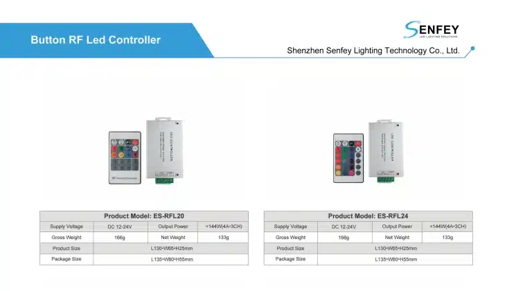
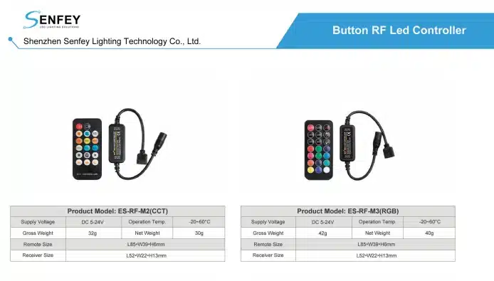
Senfey’s single-colour planning covers the 11-Key RF Single Color Dimmer Controller (2A/6A) at 12V/24V, the 14-Key RF Single Color Dimmer Controller where more scene keys are wanted, and the Touch Single Color Dimmer Controller where a fixed surface-mounted control suits joinery better than a handset. The 2A and 6A variants exist precisely because this is a current decision — check the figure against your calculation. Accessory rating interacts with the rest of the wiring, covered in the cob led strip connector guide.
Why the Bottom of the Range Is the Hard Part
Everything works at 100%. Dimming systems are judged in the bottom tenth of their range, and that is where the failures discovered at commissioning live. Four are worth naming, because each has a different cause and fix.
| Symptom at low output | Cause | Fix |
|---|---|---|
| Run drops out entirely below a level | Driver cannot regulate at very low load | Check the driver’s stated minimum, not just the controller’s |
| Visible steps instead of a smooth fade | Too few discrete levels near the bottom | Ask for resolution and whether the curve is logarithmic |
| Zones at the same setting differ | Separate drivers do not track identically | Group one visual line onto one driver where possible |
| Flicker appears only when dimmed | Longer off period in each PWM cycle | State a modulation limit and test on camera |
The third row is a design decision, not a component fault. A continuous ceiling line split across three drivers can look even at 50% and show visible steps between the thirds at 5%, since small differences in each driver’s low-end behaviour become proportionally large, and on an unbroken line the eye compares the sections directly. Where one visual line must dim as one, that argues for a single driver and controller carrying it — which loops back to the load arithmetic.
The second row is worth asking about explicitly. Human brightness perception is roughly logarithmic, so a controller dividing its range into equal linear steps gives coarse jumps at the bottom and imperceptible ones at the top. A logarithmic curve puts resolution where the eye needs it. That is a firmware property, invisible on a datasheet, exposed only by a slow fade to off.
Channel Count Decides the Controller
“Dimming” means different things depending on how many independent circuits the strip contains, and a controller built for one channel count cannot drive another. This is a hard incompatibility, not a performance difference.
- Single colour, one channel. Brightness only. The simplest case and the one the products above address.
- Tunable white, two channels. Warm and cool circuits — typically 2700K and 6500K — driven in opposition, so the controller sets a level and a mix. A single-colour dimmer lights both together and loses the CCT control entirely.
- RGB, three channels. Colour mixing, with brightness as a consequence of the three levels rather than a separate axis — see the rgb cob led strip guide.
- RGBW or RGBCW, four or five channels. A dedicated white circuit alongside the colour ones, because mixed white from RGB is neither efficient nor colour-accurate.
- Addressable, one data line. Not multi-channel dimming at all — a data protocol where each pixel or group is set individually, covered in the addressable cob led strip guide.
Two points catch buyers out. Dim-to-warm is a tunable-white product, not a dimming setting: the warming happens because the controller shifts the mix between two CCT channels as the level drops, so it cannot be retrofitted to a single-colour strip by changing the dimmer. And an addressable system needs its own controller class however simple the intended effect, because the strip expects data rather than a modulated supply.
Where the project is white light and the CCT choice itself is open, that decision interacts with the dimming plan — a warmer fixed CCT often removes the need for dim-to-warm, as set out in the warm white cob led strip guide.
Standalone Control or Building Control
The second architectural decision is whether the lighting answers to itself or to the building. It is frequently deferred, and deferring it defaults the project to standalone hardware that cannot later be integrated.
Standalone control — RF handset, touch plate, wall dimmer — needs no commissioning and no control cabling beyond the low-voltage run. It suits cabinets, joinery, single rooms and fit-outs where nobody will want central scheduling. Its limits are equally clear: no schedules, no central override, no integration with occupancy or daylight sensing, and each zone controlled from its own device.
Building control inverts that. A 0–10V driver responds to an analogue signal: simple but unidirectional, since the driver cannot report back. A digital addressable bus gives each driver its own address, so scenes, schedules, grouping and fault reporting all become possible, and the DALI Alliance documents that protocol. The cost is a commissioning stage: addresses assigned, groups programmed, scenes recorded. That is engineering time on site, not a box.
Mains-side phase control deserves a warning. It dims the mains feeding the driver rather than the driver’s output, so it requires a driver explicitly rated for it. Combining phase control with a driver not designed for it is where buzzing, low-level dropout and shortened driver life come from — and the driver is what makes the strip circuit a SELV system under IEC 61140, so substituting it on site is a safety decision as well as a control one.
Where This Decides Projects
The same three questions decide every dimmable cob led strip layout — where the dimming sits, how many channels, how low it has to go — but they give different answers by project type.
Restaurants and bars
The lighting has to change through the day, and the evening setting is often very low, which puts the whole weight on low-end behaviour rather than peak output. Where colour is part of the concept the channel count rises and brightness stops being a single axis. Project references include rgb cob led strip restaurant lighting and bar counter RGB COB LED strip lighting. Audible noise matters more than buyers expect in a quiet dining room.
Conference rooms and offices
Scene recall is the requirement — presentation, meeting, cleaning — which means building control rather than a handset, decided before drivers are ordered. Tunable white adds a second channel and doubles the tracking problem, since the two circuits must hold their mix as the level falls. See conference room tunable white LED strip lighting, and coordinate with the wider commercial office LED lighting requirements, since lighting control in these spaces is rarely specified independently.
Cabinets and joinery
Low current, one channel, one zone, no integration — the case where standalone control is correct rather than a compromise. The real constraints are physical: where the control device mounts, whether it stays reachable, and whether the level survives a power cut. A touch plate on the carcase suits a joinery shop better than a handset that gets lost.
Testing It and What to Send
A demonstration at full output proves nothing, because every failure mode here appears at the bottom of the range. Test the assembled combination — strip, driver, controller, cable length — not the strip alone.
- Fade slowly from 100% to off and watch for steps rather than a smooth curve.
- Find the level at which the run drops out, and record it. That number is the real bottom of the range.
- Point a phone camera at the strip at 10% output and look for banding. This is the flicker test.
- Listen at mid-range in a quiet room, with the driver in its intended position.
- If the layout uses more than one driver, set every zone to the same low level and compare them side by side.
- Cut power and restore it: check whether the level is remembered, if that matters.
- Test with the actual cable length between controller and strip, not a bench lead.
Send a supplier the load and the control intent: watts per metre and total metres, voltage, channel count, whether control is standalone or a building protocol, the lowest level required, the number of independent zones, and the ambient temperature at the driver position. Those determine controller rating and driver type.
Ask in return for the driver’s minimum dimming level as a percentage, the PWM frequency, whether the curve is linear or logarithmic, the controller’s current rating per channel, and whether level memory survives power loss. Efficiency context for the driver side is in the U.S. Department of Energy LED lighting guide.
FAQ
Are COB LED strips dimmable?
The strip imposes almost no constraint — it follows whatever the supply gives it. Dimming quality belongs to the driver and controller. What to settle is whether dimming happens downstream of the driver, needing an inline controller, or upstream, needing a driver specified for the control protocol.
Why does my strip cut out at low brightness?
The driver cannot regulate below a certain load, and that minimum is a driver property, not a controller one. Ask for it as a percentage before ordering. If the design needs to reach very low levels, the driver has to be selected for that specifically.
Does dimming change the colour temperature?
Not with PWM. The LED runs at full current whenever it is switched on, so the spectrum does not shift. Dim-to-warm is a two-channel tunable-white product where the controller shifts the mix between two CCTs as the level falls — it cannot be added by changing the dimmer.
What size dimmer do I need?
Calculate current, not length: watts per metre times metres, divided by voltage, then leave headroom to about 80% of rating. A 96 W load is 4 A at 24V but 8 A at 12V, so the same 12 W/m strip needs a different controller depending on voltage.
Send the Load and the Scenes
Dimming is specified from the load and the control intent. Send watts per metre and total metres, voltage, channel count, the number of independent zones, whether control is standalone or a building protocol, and the lowest level the design has to reach — controller rating, driver type and zone grouping all follow. Contact Senfey with those and we will match the driver and controller to the calculation rather than to the word dimmable.
