
LED strip accessories · Shenzhen factory
LED Strip Accessories, Power Supplies and Controllers
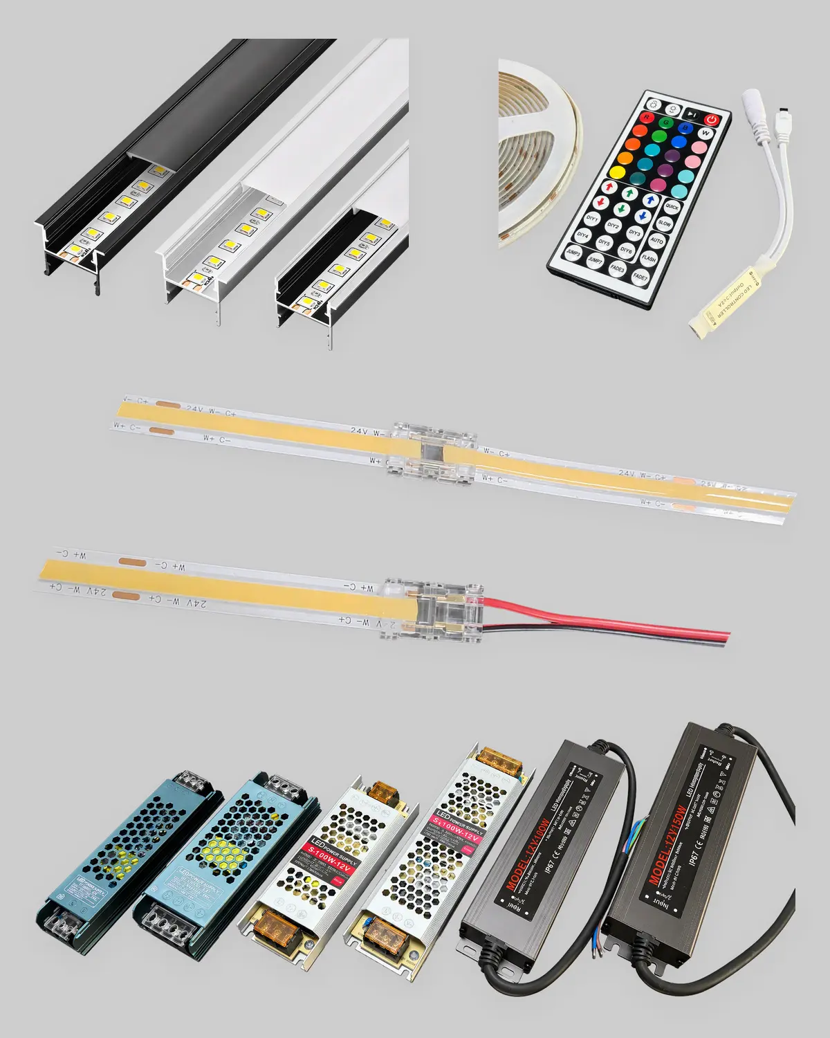
Meanwell drivers, aluminium profiles, dimmers and DMX decoders, and IP67 connectors — specified against the strip they have to run. Send the run lengths and we return a priced bill of materials, not a parts list you have to cross-check yourself.
- Driver brand
- Meanwell
- Sizing margin
- ×1.2 headroom
- Protocols
- 4 DALI · 0–10V · DMX · PWM
- Sealed parts
- IP67 / IP68
Why the accessories decide the install
Almost every strip failure we are sent is an accessory fault
The strip itself rarely fails. What fails is a driver run at its limit, a dimmer that cannot talk to the driver, a strip with nowhere to dump its heat, or a joint that let water in. Four decisions, all made after the strip was already chosen.
Symptom
Lights dim after an hour, then drop out
A driver loaded to 100% of its rating runs hot, folds back, and eventually shuts down. Electrolytic capacitors then age fast at that temperature.
Cause: no sizing headroom. Multiply the load by 1.2 and pick the next size up — see the power supply calculator.
Symptom
Dimmer works, but flickers or won't go low
The strip does not dim — the driver does. A mains phase dimmer in front of a constant-voltage driver gives flicker and a hard cut-off around 20%.
Cause: protocol mismatch. Fix the protocol before the strip — see the control protocol table.
Symptom
Brightness and colour drift along the run
Copper resistance drops volts along the strip. Past roughly 5 m on 12V the far end is visibly dimmer and warmer than the feed end.
Cause: voltage drop. Move to 24V, or inject power at both ends — see wiring and voltage drop.
Symptom
Outdoor run fails in the first wet season
Sealed strip with an unsealed joint is an unsealed system. Water tracks in at the cut end or the DC barrel and corrodes the copper.
Cause: the joint, not the strip. Match the connector IP to the strip — see the connector and IP table.
The four parts are one chain
Power, control, thermal and sealing each have to match the strip and each other. Get one wrong and the run underperforms regardless of the other three.
What we supply
Four groups, specified against the strip
Not a catalogue to browse. Tell us the strip, the run lengths and how the space is controlled, and these four groups get filled in as one matched set.
Group 01
Power supplies and drivers
Meanwell as standard — global certification, five-year warranty, and a failure record we can stand behind.
- HLG series — IP67, potted, for facade and landscape runs
- LRS series — indoor slim metal case, the cost-effective default
- ELG series — IP67 with dimming built in, 0–10V / PWM / DALI
- 24V preferred on project work, less drop over distance
Sized at 1.2× the calculated load — see the calculator.
Group 02
Controllers and dimming
The strip does not dim, the driver does. Agree this group with whoever commissions the building system, not at the end.
- Single colour dimmers — PWM, with RF or Wi-Fi remote
- RGB / RGBW controllers — for colour-change zones
- DMX512 decoders — architectural scenes and show control
- DALI and 0–10V — where a BMS drives the lighting
Match protocol to driver first — see the protocol table.
Group 03
Aluminium profiles and diffusers
Three jobs at once: pull heat out of the strip, soften the light, give the installer something to fix to. Mandatory on project work.
- Surface U-channel — screw or adhesive, under-cabinet and shelf
- Recessed T-channel — flush into plaster or joinery
- Corner 45° — cove and perimeter details
- Diffusers — frosted for dot control, clear for maximum output
Profile width follows strip width — see the width guide.
Group 04
Connectors, seals and mounting
A sealed strip with an unsealed joint is an unsealed system — the most common cause of an outdoor run failing in year one.
- Solderless clips — 2/4/5/6 pin, indoor, fast strip-to-strip
- IP67/IP68 joints — gasketed cable-to-cable for wet locations
- Silicone end caps — seal every cut end outdoors
- Mounting clips and channel — fixings, not adhesive alone
Soldered joints outperform clips on long runs — connector guide.
Power supply sizing
How to size the driver, and why 1.2 is not optional
An undersized driver runs hot, folds back and dies early. A wildly oversized one wastes money and space in the ceiling void. The arithmetic below is the whole method — it takes about a minute, and it is the single most useful thing on this page.
Required driver wattage
The 1.2 is thermal and ageing headroom, not a safety fudge. A driver held at 100% load has nowhere to go on a hot day.
Why 24V, and why feed from both ends
Copper resistance costs volts along the strip. The far end of a long 12V run is visibly dimmer and warmer in colour than the feed end.
Worked example — 20 m of 2835 strip
- Read the strip wattage. A 120 LEDs/m SMD 2835 strip draws about 9.6 W per metre. Take this from the datasheet, never from the reel label alone. 9.6 W/m
- Total the run length that this one driver will feed. Do not total the whole project — total the circuit. 20 m
- Multiply out and add headroom. 9.6 × 20 × 1.2. = 230.4 W required
- Pick the next standard size up. Outdoor: Meanwell HLG-240H-24 at 240 W. Indoor with room to spare: LRS-350-24 at 350 W. 240 W outdoor / 350 W indoor
- Check the run length against the voltage. 20 m is well past the 5 m limit, so this is 24V, split into sections, fed at both ends. 24V, both ends
Driver selection at a glance
Which Meanwell family fits which situation. If the room is dimmed from a building system, the driver has to be chosen for the protocol as well as the wattage — that is the next section.
| Series | IP rating | Dimming | Typical wattage | Specify it for |
|---|---|---|---|---|
| HLG | IP67 | Optional B-type | 60–600 W | Facade, landscape, parking, anything exposed or in a damp void |
| LRS | IP20 | None | 35–350 W | Indoor plant rooms and ceiling voids on a switched circuit |
| ELG | IP67 | 0–10V / PWM / DALI | 75–240 W | Exterior or damp locations that also have to dim |
| Slim indoor | IP20 | TRIAC or 0–10V | 30–150 W | Joinery and cabinetry where driver depth is the constraint |
Scroll the table sideways on narrow screens to see every column.
Control and dimming
Pick the protocol first, then the driver
LED strip does not dim itself. Something upstream varies what reaches it, and it has to speak the same language as the rest of the building. Get the order wrong and a correctly specified strip flickers, steps, or will not go below 30 per cent.
1
Ask who controls the light
A wall plate, a lighting console, or a BMS. That answer decides the protocol, and the protocol decides everything after it.
2
Choose the driver for that protocol
Dimming is a driver capability, not an add-on. An LRS cannot be made to dim later.
3
Count channels, then the decoder
One channel per single-colour zone, three for RGB, four for RGBW, five for RGB + CCT. Size the decoder to the channel count and the zone wattage.
| Protocol | How it reaches the strip | Zones and channels | Specify it when | Watch out for |
|---|---|---|---|---|
| DALI | Digital bus to a DALI driver, which varies its own output | Addressable per driver, regroup in software | A BMS or a commissioned lighting system runs the building | Bus polarity and address planning have to be agreed with the commissioning engineer |
| 0–10V / 1–10V | Analogue pair into a dimmable driver | 1 per driver | Simple, robust dimming with no commissioning overhead | Long analogue runs pick up noise; keep the pair away from mains |
| DMX512 | Console or controller to a DMX decoder, decoder to the strip | Up to 512 per universe | Colour change, scenes, show control, synchronised facades | Universe budgeting and terminated daisy chains, not star wiring |
| PWM | Constant-voltage dimmer switching the DC feed on and off fast | 1 to 5 | Cove, cabinet and joinery lighting on a local remote | Low PWM frequency shows on camera; specify a high-frequency unit |
| TRIAC | Mains-side dimmer feeding a TRIAC-compatible driver | 1 per circuit | Retrofit into an existing mains dimmer you cannot replace | Driver and dimmer must be a tested pair, or expect flicker and buzz |
Scroll the table sideways on narrow screens to see every column.
One thing that catches almost everyone
Whatever the protocol, the strip still wants clean constant-voltage DC. Dimming happens before the strip, never on it — there is no such thing as a dimmable strip, only a dimmable driver feeding it. Where the control spec arrives late we default to an ELG. Hotel work hits this most often, which is why the hotel lighting page treats control as part of the specification.
Profiles, joints and sealing
The parts that decide whether the run survives year one
Drivers get specified carefully because they cost money. Profiles and connectors get left to site because they do not — and that is where the callbacks come from.
Aluminium profiles: pick the width from the strip, not the look
The channel has to clear the strip plus its silicone jacket, or the strip bows and the adhesive lets go in a warm ceiling. A 10 mm IP20 strip and a 10 mm IP65 strip are not the same width once potted.
| Profile | Takes strip | Fixing | Use it for |
|---|---|---|---|
| Surface U | 8–12 mm | Screw or clip | Under-cabinet, shelf, exposed cove |
| Recessed T | 8–12 mm | Plaster-in or routed | Flush ceiling and joinery lines |
| Corner 45° | 8–10 mm | Screw into the angle | Perimeter coves, indirect wash |
| Wide / deep | 12–20 mm | Screw | High-output and wide COB tape |
Wide tape needs a wide channel — the wide COB strip guide lists the actual jacket dimensions.
Connectors and seals: match the joint to the location
Solderless clips are quick and fine indoors. Outdoors they are the weakest point in the system, because the clip breaks the silicone jacket and nothing puts it back. Anything exposed gets a gasketed IP67 coupler, or is soldered and re-sealed.
| Joint method | Rating achieved | Install | Current | Where it belongs |
|---|---|---|---|---|
| Solderless clip | IP20 | Hand, no tools | Light | Dry indoor runs, short lengths, fast fixes on site |
| Soldered and heat-shrunk | IP20–IP65 | Iron on site or pre-made | Full | Long indoor runs, anything carrying real current |
| IP67 gasket coupler | IP67 | Screw together, no tools | Full | Facade, landscape, bathroom and external cove |
| IP68 potted joint | IP68 | Factory potted to length | Full | Submerged, pool surrounds, permanent buried runs |
| Silicone end cap + glue | IP65–IP67 | Glue and cure | — | Every cut end outdoors, without exception |
Scroll the table sideways on narrow screens to see every column.
Four rules we will not quote around
- Cut ends outdoors get capped and glued. An open end wicks water down the copper and takes the section with it.
- The joint rating caps the system rating. IP68 strip plus an IP20 clip is an IP20 installation.
- Solder anything long. Clips add contact resistance, which on a long run shows as a visible dim step.
- Profiles are a thermal part, not a trim. Strip with no heat path loses output early and shifts colour with it — see the installation guide.
Wiring and voltage drop
How the run gets fed, and where the limit sits
Copper has resistance, so every metre of strip costs a little voltage. Because an LED’s output and colour both move with current, the far end goes dimmer and warmer. Nothing about the strip is faulty — the layout is.
Single-end feed
One driver, one connection at one end. Simplest to install, and what most drawings show.
Limit: about 5 m on 12V, 10 m on 24V
Both-ends feed
Same driver, cable run to each end. The drop meets in the middle instead of piling up at one end, so the run stays even.
Roughly doubles the usable length
Sectioned home runs
Long runs split into sections, each fed on its own cable. More cable and labour, and the only method that holds past 20 m.
The only option on facade and cove runs
The three layouts, drawn
Solid orange is full voltage. Where the bar fades, the strip is below spec — that is the part a client notices from across the room.
Practical length limits and feed cable
What we work to on project quotations, for a typical 10–15 W/m strip. Higher-output tape pulls these numbers down, so send the actual W/m.
| Strip voltage | Single-end max | Both ends fed | Feed cable | Where it fits |
|---|---|---|---|---|
| 12V | 5 m | 10 m | 1.0–1.5 mm² | Cabinets, display cases, short retrofit lengths |
| 24V | 10 m | 20 m | 1.5–2.5 mm² | The project default — coves, joinery, corridors |
| 24V sectioned | 10 m per section | no practical limit | 2.5 mm² trunk | Facades, long perimeters, landscape runs |
| 48V | 25 m | 50 m | 1.5 mm² | Long uninterrupted architectural lines |
Scroll the table sideways on narrow screens. On 12V versus 24V the decision is almost always distance — the 24V strip page covers why we push 24V on anything architectural.
What you get back
A worked bill of materials, not a parts list
This is the shape of what we return. You send the run lengths and how the space is controlled; we send back every line with the quantity already worked out, so your estimator checks a number rather than builds one.
The enquiry this came from
Simplified from a real enquiry: hotel corridor and lobby cove, dimmed from the building system, plus one external canopy detail.
- Total strip
- 86 m
- Longest single run
- 18 m
- Control
- DALI from BMS
- Locations
- Indoor + 1 external
| Line item | Specification | Qty | Why this quantity |
|---|---|---|---|
| Power | |||
| Indoor driver | Meanwell ELG-150-24, IP67, DALI | 6 | 68 m indoor at 9.6 W/m × 1.2 = 784 W; split by zone, not by total |
| External driver | Meanwell HLG-240H-24, IP67 | 1 | 18 m canopy at 9.6 W/m × 1.2 = 207 W, next size up |
| Control | |||
| DALI power supply | Bus PSU, 250 mA | 1 | One bus segment covers all seven drivers on this floor |
| Commissioning allowance | Addressing and grouping | 1 lot | Flagged so it lands in someone’s scope instead of nobody’s |
| Thermal and optical | |||
| Recessed T profile | 2 m lengths, 12 mm channel | 44 | 86 m ÷ 2 m = 43, plus one for cutting waste |
| Frosted diffuser | 2 m, matched to profile | 44 | One per profile length; frosted to hide the dots in a corridor |
| Mounting clips | Steel, screw-fixed | 180 | Roughly one every 500 mm — adhesive alone is not a fixing |
| Joints and sealing | |||
| Solderless clip, 2-pin | Indoor, 10 mm | 24 | Indoor strip-to-strip only; long runs are soldered instead |
| IP67 coupler | Gasketed, cable-to-cable | 6 | Every joint on the external canopy, including the driver tail |
| Silicone end cap + glue | IP67, 10 mm | 8 | Every external cut end, capped and cured — no exceptions |
| Feed cable | 2-core, 2.5 mm² | 140 m | Both-ends feed on all runs over 10 m, so cable roughly doubles |
| Lines on the finished BOM | 11 | Priced, with lead time per line | |
Scroll the table sideways on narrow screens to see every column.
Four things we check before the BOM goes out
The questions a parts list never answers — and the reason a BOM beats a price sheet.
- Does the driver dim the way the building does? An LRS cannot be retrofitted to DALI. If control is anywhere in the brief, the driver family changes.
- Is any run past its voltage limit? Anything over 10 m on 24V gets fed at both ends or sectioned, and the cable quantity rises with it. Priced in, not discovered on site.
- Does every joint match the wettest location it sits in? The system rating is its lowest-rated component. One indoor clip on an external run makes the whole run IP20.
- Is the profile wide enough for the strip as jacketed? A 10 mm IP65 strip does not fit a 10 mm channel. We check against the strip actually being supplied, including wide COB tape.
Procurement and factory support
Getting a priced accessory BOM from the factory direct
Senfey manufactures LED strip in Shenzhen and supplies the accessories against it, so a question about driver headroom or an IP68 joint is answered by the people building the run. We supply contractors, specifiers and distributors, not retail.
- Send the strip and the run lengths
- The W/m, the voltage, and the length of each continuous run. That is the minimum needed to size drivers.
- Tell us how the space is controlled
- Wall plate, DALI from a BMS, DMX console, or switched only. This decides the driver family, so it cannot wait until after the order.
- We size drivers and split the zones
- Load × 1.2, then split by zone rather than by total, so one failure does not take a whole floor with it.
- Profiles, joints and sealing get matched
- Channel width against the jacketed strip, and joint rating against the wettest location each run passes through.
- You get a priced BOM with the working shown
- Every line has a quantity, the reason for it, and a lead time.
- OEM, ODM and market certification
- Pre-made lead sets, cut-to-length runs, custom connector configurations, private labelling. Name the destination country, because driver approvals differ by market: about Senfey.
What speeds it up most
- W/m and voltage of the strip — not the brand name, the actual figures
- Longest continuous run, which is what decides feed method and cable
- Which runs are outdoors or in a damp void, even if only one of them is
- Who commissions the control, if anyone — a name is enough
A drawing helps but is not required — run lengths on an email are enough.
Request a project BOM
Send the run lengths and how the space is controlled. We reply with a priced bill of materials — drivers, profiles, joints and cable, with the quantity working shown. Prefer email? Use the contact page.
Drawings and strip datasheets help but are not required — attach them by email.
FAQ
Accessory and power supply questions we get asked
The questions that come up while an installation is being priced — mostly from people who have been caught once already.
How do I work out what size power supply I need?
Multiply the strip wattage per metre by the total metres on that driver, then by 1.2. A 20 m run of 9.6 W/m strip is 230.4 W, so specify the next standard size up.
The 1.2 is not padding. A driver held at 100 per cent runs hot, and heat is what kills capacitors — roughly 80 per cent load is the difference between a five-year life and a two-year one.
Why Meanwell rather than a cheaper driver?
Because the driver is the part that fails, and on a project the cost of failure is access rather than hardware. Replacing a cheap driver above a finished plaster ceiling costs a scaffold and a client conversation.
Meanwell carries global certification and a five-year warranty, which also matters when the specification has to be signed off by someone who was not in the room.
Can I make a non-dimmable strip dimmable later?
The strip was never the issue — constant-voltage strip dims from whatever feeds it. What you cannot do is make a non-dimmable driver dim. An LRS has no control input, so adding dimming means changing the driver.
If control is even a possibility, specify a dimmable driver from the start — see the protocol table.
My dimmer makes the strip flicker. What went wrong?
Almost always a protocol mismatch. A mains TRIAC dimmer in front of a driver not designed for one gives flicker and a hard cut-off around 20 per cent, because the driver is trying to regulate a chopped input.
The other version is a low-frequency PWM dimmer that looks fine to the eye but bands badly on camera. Specify a high-frequency unit.
Why does the far end of my run look dimmer and warmer?
Voltage drop. Every metre of copper costs a little voltage, and LED output and colour both move with current. Past roughly 5 m on 12V or 10 m on 24V it is visible.
Fix it with layout, not a bigger driver: move to 24V, feed from both ends, or split into sections with their own home runs. The wiring section shows all three.
Are solderless connectors good enough for a project?
Indoors on short runs, yes — fast, and they hold. On long runs the added contact resistance shows as a visible step in brightness, so we solder instead.
Outdoors they are the wrong part. The clip pierces the silicone jacket and nothing reseals it, so water tracks into the copper. Use a gasketed IP67 coupler and cap every cut end — see the connector guide.
Do I really need aluminium profile, or is the adhesive backing enough?
On project work we treat profile as mandatory. It pulls heat out of the strip, diffuses the light into a line instead of dots, and gives the installer something mechanical to fix to.
Adhesive backing is a positioning aid, not a fixing. In a warm void the tape relaxes and the strip sags, and with no heat path it loses output and shifts colour as it goes.
Does IP68 strip give me an IP68 installation?
No. The system rating is that of its lowest-rated component. IP68 strip joined with an IP20 clip is an IP20 installation, and it fails in the first wet season.
Every joint, cut end and driver entry has to match the wettest location the run passes through — see the connector and IP table.
Can you supply accessories without the strip?
Yes. Plenty of enquiries are drivers and profile only, for strip already bought or installed. Tell us the W/m and the voltage and we size against it.
It works better together, because then we can check channel width against the actual jacketed strip rather than guessing from a product code.
Still working out what a run needs? Send the strip specification and the run lengths. We come back with a priced bill of materials, quantity working shown.
Request a project BOM