
Most questions about how to install cob led strip lights arrive as wiring questions, but the failures that reach a snag list are rarely wiring failures. They are sizing and sequencing failures: a driver loaded to its rating, a run fed from one end when it needed two, adhesive pressed onto a dusty MDF edge, or a section tested only after the ceiling was closed. The strip itself is usually blameless.
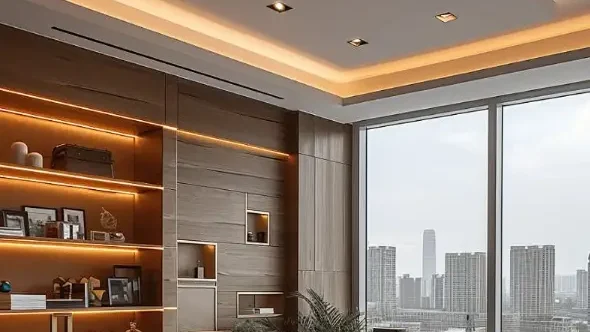
This guide covers the decisions that have to be made before power is applied, written for contractors, project engineers, and procurement teams specifying COB LED strip for hotel, commercial, cabinet, spa, corridor, and architectural work. Mains-side work and building electrical integration remain the responsibility of a qualified electrician under local code; everything below concerns the low-voltage side.
The Installation Sequence, and Why the Order Matters
The order of these steps is not arbitrary, and it is the part of how to install cob led strip lights that datasheets never cover. Each step closes off a decision that becomes expensive to reverse once the next one is complete.
- Confirm the strip model: voltage, wattage per metre, CRI, colour temperature, IP rating, PCB width, and cut interval in millimetres.
- Mark out the run on the actual substrate and divide it into electrical sections before cutting anything.
- Calculate total load, size the driver with headroom, and fix the driver position and its service access.
- Confirm the profile, its internal width, and that connectors will physically fit inside it.
- Prepare and clean the mounting surface.
- Cut at marked points only, and make the joints.
- Power up and test every section while the strip is still loose.
- Bed the adhesive or fix the profile, then re-test before anything closes over it.
Step 7 is the one most often skipped, and it is the one that saves money. A loose strip that fails a test costs minutes. The same fault found after the strip is bonded into an aluminium profile usually means destroying the strip to get it out, and often marking the profile finish in the process.
On longer commercial runs a 24V layout gives more voltage headroom per section than the 12V equivalent, which reduces how many feed points step 2 has to produce.
Driver Sizing, Headroom and Where the Driver Lives
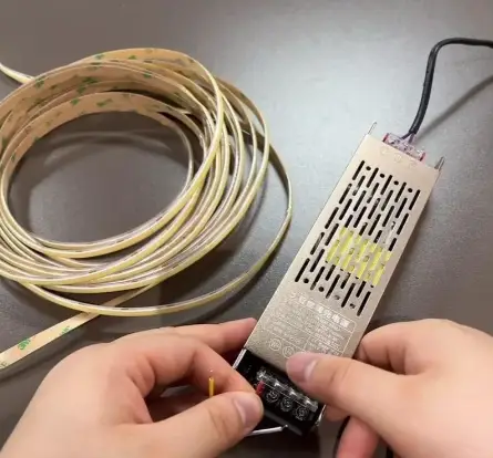
Total load is straightforward: watts per metre multiplied by installed metres, summed per driver. The part that gets skipped is headroom. Common practice is to load a driver to around 80% of its rated output rather than to its maximum, because a supply running continuously at full rating runs hotter, and driver heat is a leading cause of premature failure and of flicker appearing months after handover. On a 60 W calculated load that means a 75 W driver, not a 60 W one.
Ambient temperature belongs in the same calculation. A driver rated at 25 °C ambient does not deliver the same figure sitting in a sealed ceiling void above a hot cove, so either derate it or ventilate the space it sits in.
Driver Position Is a Maintenance Decision
Drivers are the shortest-lived component in the system. The strip may run for years while the driver needs replacing well before it, so the driver position should be chosen as though it will be replaced — because it will. That means a serviceable location reachable through an access panel, a removable joinery plinth, or above a demountable ceiling tile, and it means a driver never buried behind plasterboard that has to be cut open.
In wet areas the rule is firmer. Keep drivers outside the wet zone entirely and run low-voltage cable in to the strip, with the driver in an adjacent dry, ventilated, accessible position. A bathroom and spa waterproof COB project shows how those zones and driver positions are separated in practice.
Voltage Drop and Feed Strategy
Have an LED Lighting Project?
Share your project requirements — our engineering team will configure the complete LED strip system (strips + profiles + controllers + power supplies) and send you a detailed proposal within 24 hours.
Voltage drop is what makes the far end of a cove read dimmer and slightly warmer than the near end. It is cumulative along the strip and along the cable feeding it, and a common design limit is to hold the drop at the far end within about 10% of nominal — beyond that the difference becomes visible when the two ends of a run are seen together.
Three levers control it, and they are worth using in this order:
- Feed from both ends. The cheapest fix available. Injecting at both ends of a run roughly halves the worst-case drop compared with a single end feed, and it needs no extra driver — only a second cable back to the same output.
- Break the run into sections. Several shorter parallel sections from one driver behave far better than one long series run, and they also localise any future fault.
- Increase the cable size. Cable between driver and strip carries the full section current, so an undersized run of thin flex can waste voltage before the strip even starts. This is a common and easily missed cause.
Confirm the manufacturer’s maximum single-run length for the specific product rather than assuming a figure, since it changes with wattage per metre and copper thickness. Then verify on site: measure the voltage at the far end of each section under full load before the run is closed up. It takes a minute per section with a multimeter and it is the only way to know the calculation held.
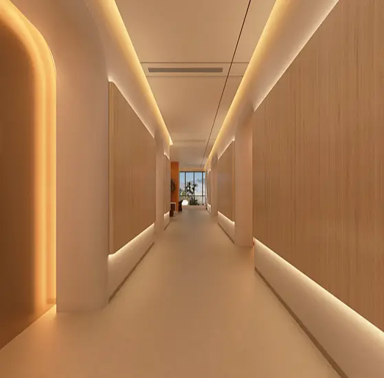
On long corridors the same planning also determines where dimming zones break. A hotel corridor linear run shows how feed points, driver positions, and zone boundaries end up aligned, and the hotel corridor lighting page covers the layout side of that.
Mounting: Surface Preparation and the Profile as a Heat Sink
Adhesive failure is the most common callback on strip installations, and it is almost always a preparation problem rather than a tape problem. Three conditions matter and all three are routinely missed on site.
The surface has to be genuinely clean — isopropyl alcohol on bare metal or sealed timber, not a dry wipe, since dust, release agents, and machining oil on freshly cut MDF all defeat acrylic adhesive. The tape needs firm pressure along its whole length as it is applied, because these adhesives bond by wetting the surface under pressure rather than by contact alone. And they need temperature and time: applying in a cold unheated shell gives a weak initial bond, and full bond strength typically develops over the following day or two rather than immediately. A strip that will be handled, cut, or adjusted right after being stuck down should be fixed mechanically instead.
Unsealed plasterboard, dusty concrete, and raw timber are poor bonding surfaces regardless of preparation. On those, use a profile or clips and let the adhesive do nothing structural.
The Profile Is Doing Thermal Work
Because COB needs little optical diffusion, it is easy to conclude it needs no profile. The opposite is true. A COB strip generates heat continuously along its entire length with no cool board between chips to spread it, so at any given wattage it has less self-cooling than a discrete-package strip. The aluminium profile is what carries that heat away.
This makes profile contact a functional requirement, not a cosmetic one. The strip should sit flat against the aluminium base along its full length, with no air gap or bridging over a bump. Two practices defeat it entirely: mounting a strip on a plastic channel at full output, and doubling a strip back on itself inside one profile to gain brightness, which puts twice the load into the same heat sink. Check the maximum operating temperature on the datasheet and measure the strip case temperature after an hour at full load in the real installation, not on the bench.
Confirm the profile’s internal width against the PCB before ordering. An 8 mm board in a 10 mm channel leaves working clearance either side; a 10 mm board in the same channel does not, and forcing it stresses the board edges.
Cutting, Joining and Low-Voltage Wiring
Cut at the printed marks only, with the driver disconnected, and confirm the cut interval before joinery is machined rather than after. The mechanics of cutting and bending, including minimum bend radius and re-sealing cut ends on waterproof builds, are covered in the guide to cutting COB LED strip.
Solder or Connector
Both work; the choice should be made on clearance rather than preference. A clip connector is wider and thicker than the strip it holds, so a section that fits a 10 mm groove may not accept a connector at all. Where the profile is tight, solder the joint or move it outside the profile entirely. Where sections need to be demountable for service, connectors earn their place — provided they are rated for the section current and are not the only thing taking mechanical load.
Wiring Checks Before Power
- Confirm polarity at every joint. COB strips are polarity-sensitive and a reversed section simply stays dark.
- Size cable for the section current and the cable distance, not just the current.
- Provide strain relief so no pull reaches a solder joint or a pad.
- Insulate exposed pads, particularly inside a metal profile.
- Keep the low-voltage circuit physically separated from mains wiring. These strips operate as SELV circuits per IEC 61140, and that classification depends on maintaining the separation.
Control and Dimming
Confirm the dimming protocol before ordering, because the driver has to support it and cannot be adapted later. PWM, 0–10V, DALI, and TRIAC are not interchangeable, and a TRIAC dimmer chosen for its familiarity is the usual cause of low-end flicker and audible buzz on strip installations. Where a project mixes COB with other technologies on a shared 24V infrastructure, the 24V LED strip planning guide covers the layout side.
Testing and Troubleshooting
Test at four points: on the reel before cutting, after cutting, after joining, and after mounting. Each test isolates one stage, so a fault points at a cause instead of requiring the whole run to be diagnosed at once.
| Symptom | Check First | Usual Cause |
|---|---|---|
| One section dark | Polarity, then the joint | Reversed connection or a cut made off the mark |
| Far end dimmer or warmer in tone | Voltage at the far end under load | Voltage drop: run too long, single end feed, or thin cable |
| Flicker at low dim levels | Dimmer and driver protocol match | Incompatible dimming method, or load below the driver’s minimum |
| Flicker at full output | Driver load against its rating | Driver at or over capacity, or a loose connector contact |
| Strip lifting after weeks | Substrate and application conditions | Contaminated surface, no bond pressure, cold application, or heat |
| Colour varies between runs | Reel batch numbers | Mixed production batches, or voltage drop shifting tone along a run |
The last row is worth handling at order stage rather than on site. Where runs will be seen together, request material from one batch and keep offcuts identified by reel, because two reels that each look correct alone can be visibly different side by side.
Choosing a Strip That Installs Cleanly
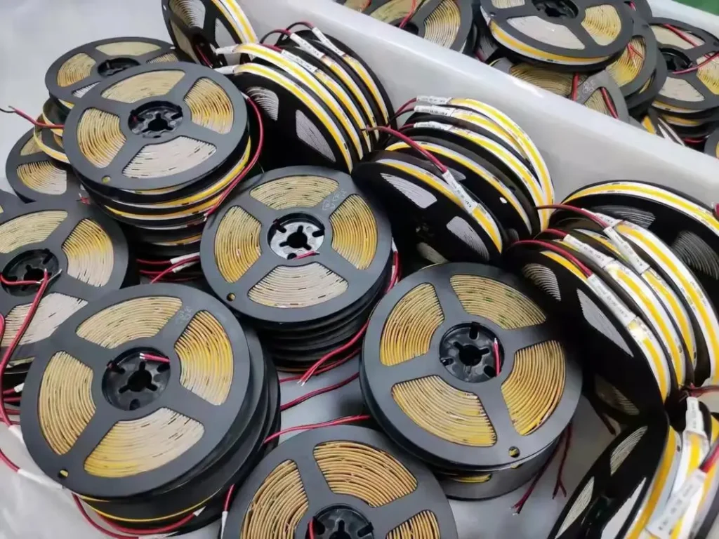
Board width and voltage decide how much trouble the installation gives. All three of these are IP20 with CRI 90 for dry, concealed positions.
- 320 LEDs/m, 8 mm board — 12V or 24V. Lower load per metre and the easiest of the three to fit into short furniture and display sections.
- 480 LEDs/m, 8 mm board — 12V or 24V. The general-purpose choice for coves, cabinets, and commercial linear runs, and it still clears a 10 mm groove.
- 528 LEDs/m, 10 mm board — 24V only. Higher density and higher output from a single run, which also means more heat per metre and a wider profile to plan around.
Where colour temperature consistency across many repeated runs is part of the brief, the warm white COB guide covers the tolerance question. Damp and exterior positions need a waterproof build specified separately, with its own sealing and driver-placement requirements.
FAQ
Can COB LED strip be installed without an aluminium profile?
In low-output positions on a suitable surface, yes. At higher wattage the profile is a thermal component rather than a finish, because COB generates heat continuously along its length with no cool board to spread it. Check the datasheet’s maximum operating temperature before deciding.
How much headroom should the driver have?
Common practice is to load a driver to around 80% of its rating rather than its maximum, and to allow for the ambient temperature where it will actually sit. A driver running continuously at full rating runs hot, and heat is what shortens its life.
How long a run can be fed from one point?
It depends on wattage per metre, copper thickness, and cable size, so confirm the figure for the specific product. Then measure the voltage at the far end under full load before closing the run up, since the calculation assumes cable sizes that site conditions do not always deliver.
Is soldering better than using connectors?
Solder is more reliable inside a tight profile, mainly because a clip connector adds width and thickness the groove may not have. Connectors are the better choice where sections must stay demountable for service.
Why did the adhesive fail?
Usually surface contamination, no bond pressure during application, application in a cold shell, or heat from an under-cooled strip. Full bond strength develops over a day or two, so a strip handled immediately after fixing has not yet reached it.
Why does the installation flicker when dimmed?
Most often a dimming protocol mismatch, or a load below the driver’s minimum. Confirm PWM, 0–10V, DALI, or TRIAC before ordering, since a driver cannot be converted to another protocol afterwards.
What should be confirmed before a bulk order?
Voltage, wattage per metre, CRI, colour temperature, IP rating, PCB width against the profile, cut interval, connector clearance, dimming protocol, driver positions, and batch consistency for reorders.
Reference Resources
For broader background on LED lighting, controls, and electrical planning:
Request Project Support
If you are planning how to install COB LED strip lights across a hotel, commercial, cabinet, spa, corridor, or architectural project, the most useful information to send is the run lengths with intended feed points, the profile section, the voltage, and the dimming method. With those we can check the driver sizing and feed strategy against your layout before anything is ordered.
You can contact Senfey for samples, driver and control matching, or a project quotation.
